Just for funsies, I had this idea in my head to try to see if I could measure how fast the Arduino Uno can process a very simple loop of code using an oscilloscope. For this experiment I wanted to toggle a pin on, then turn it off while turning another pin on, rinse, repeat. Basically toggle 2 pins off and on opposite of each other.
For the first part of the experiment I wrote the following code...
void setup() { //Setup routine (runs once)
pinMode(5, OUTPUT); //Configure I/O pin 5 as an output
pinMode(6, OUTPUT); //Configure I/O pin 6 as an output
}
// the loop routine runs over and over again forever:
void loop() {
digitalWrite(5, LOW); // turn off pin 5
digitalWrite(6, HIGH); // turn on pin 6
digitalWrite(6, LOW); //turn off pin 6
digitalWrite(5, HIGH); //turn on pin 5
}
The code above ensures that neither pin is on at the same time as the other. Using the Arduino's digitalWrite commands, I had to use a line of code to turn one pin off before I could turn another on. Here is the screenshot from the scope, the yellow signal trace represents pin5 and the blue trace is pin 6. The measurements displayed are for the channel associated with Pin5.
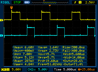
So a few interesting take aways, the maximum frequency is ~51kHz, I feel this is rather slow considering the Arduino is running at 16MHZ. The other interesting point is the +Duty% is roughly %25, this makes perfect sense considering the code is 4 parts and pin5 being only represents 1 out of the 4 lines of code, so the math works. The last thing is the massive overshoot, the waveform peaks at 6.6V and undershoots to -.4V. This seems extremely "loose" considering it is supposed to be 0-5V. I am running this board off of 12V power supply but the Arduinos onboard regulator should regulate the operating voltage down to 5V, so I am not sure what to make of this.
Moving forward, I read a chapter in the "Arduino Cookbook" that explains how to set digital pins directly by accessing the bare metal on the chip via its hardware registers. I have read that this can lead to speed increases by as much as a factor of 30. So, I decided to run the experiment again.
With this new code, being as I was manipulating the hardware registers directly, I no longer had to "waste" a line of code to turn a pin off, I could toggle the states of up to all 8 pins on PortD on or off with a single line of code. Here is what the new version of the above code looks like.
void setup()
{
pinMode(5, OUTPUT);
pinMode(6, OUTPUT);
}
void loop()
{
PORTD = B00100000; //Sets the output of ALL pins on PortD (0-7) to LOW except Digital Pin 5
PORTD = B01000000; //Sets the output of ALL pins on PortD (0-7) to LOW except Digital Pin 6
}
And here is the new waveform...
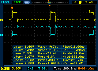
So here we have some expected and unexpected results... First, the speed has dramatically improved, The measurements indicate a 1MHz frequency. This was predicted, it works out to be about 19.5 times faster than the previous code, although I am disappointed that a 30x speed increase wasn't realized. What I did not expect is the uneven duty cycle of the 2 waveforms. Pin6 stays on 87% of the time while pin5 is only on for the remaining 13%. This represents the state of the 2nd (and last) line of code in the loop. My only thought is the MCU needs time to "Rewind" back to the beginning of the loop. It actually seems like this requires about %75 of the total time to accomplish this in this example. Were talking roughly 800nanoseconds (or 800 billionths of a second / .000,000,800 seconds), so in most use cases this is negligible.
Perhaps if I knew assembly, even more fun could be had, but for the time being, this will have to suffice. Hit me up in the comments below to let me know what you think.

 Damage | Posted on