
Custom lighting for PPG.
 Damage | Posted on
 I started to design a custom lighting driver to drive and control 255LEDs + a LED strobe on my Paramotor. Here is a breif video of them in action.
The design consists of 3 major components. The battery, The driver box and the keypad control box. The way i currently have it programmed is as follows. Numbers 0-9 switch different patterns. The * key acts as a "shift" so * followed by a number gives me 10 additional patterns. If I outgrow this, I can rethink this, but for now it seems to work ok. The # key toggles the strobe on or off. My design uses 2 ATMEGA328 microprocessors. The idea is, 1 processor is dedicated to running the strobe, so the strobes timing is independant of anything going on with the ring lights. The second processor polls the keypad over i2c and runs the ring lights. Additionally, processor 2 toggles a pin high or low which acts as a signal that processor 1 is listening for to determine if the strobe should be on or off.
Going with 2 separate processors significantly reduces the processing load as opposed to trying to do it on 1 chip. The keypad is a nifty thing that sparkfun came up with called the "Quiic Keypad", this is nice because it talks over i2C and handles all the keypad matrixing/polling, further reducing processor load of my main processors.
There was 1 issue with using The sparkfun keypad. It operates at a 3.3V logic level and my stuff operates at 5V. So I threw in a local VREG and a logic level converter to handle this descrepancy. Finally I connectorized everything so that I can quick disconnect any given component if I need to. The connectors are all keyed and different, so it's impossible to accidentally connect the wrong component to any given connector.
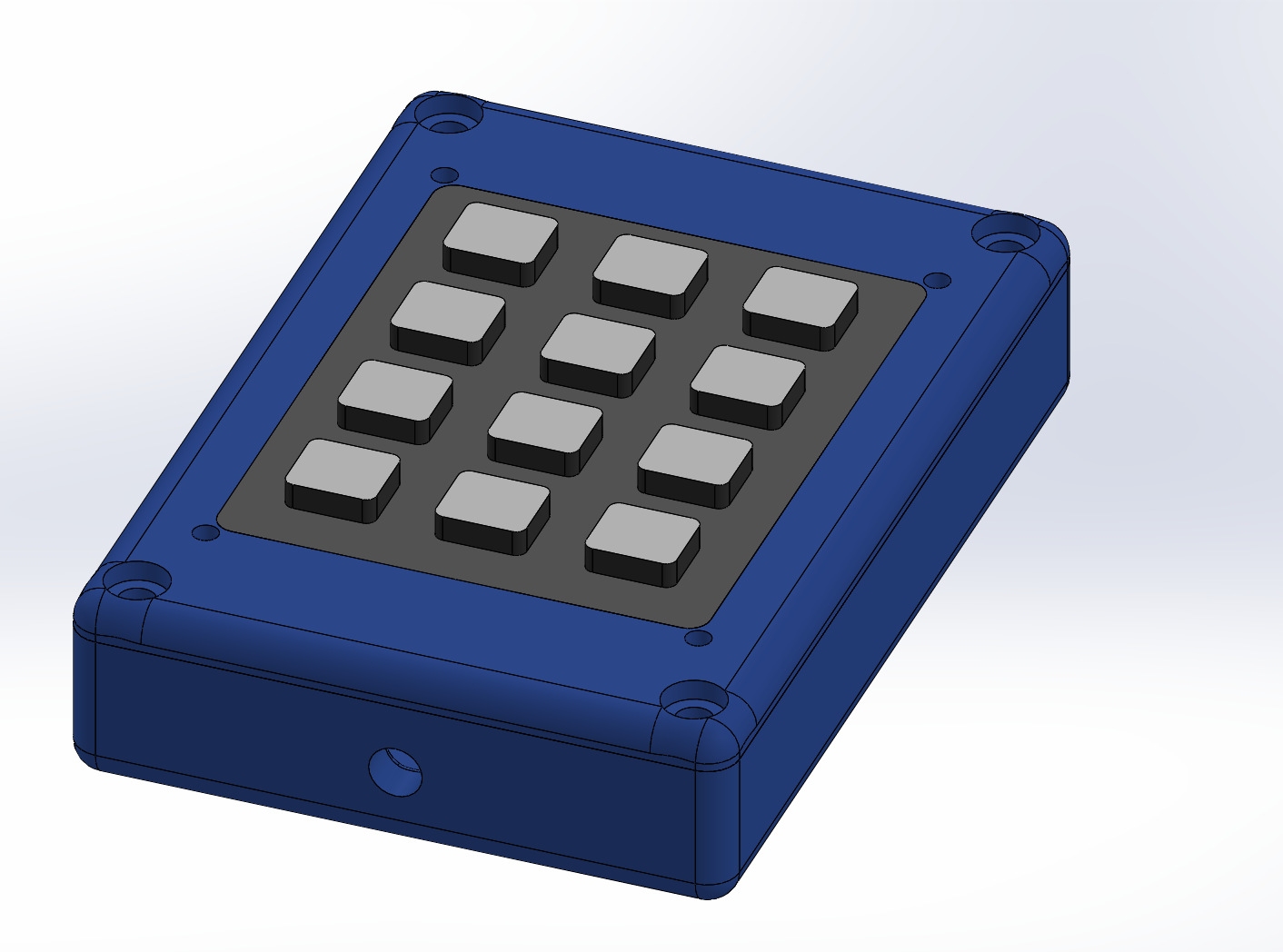
Finally, I designed in Solidworks and 3D printed custom enclosures for the driver and keypad boxes.
Here are a few photos of the build...
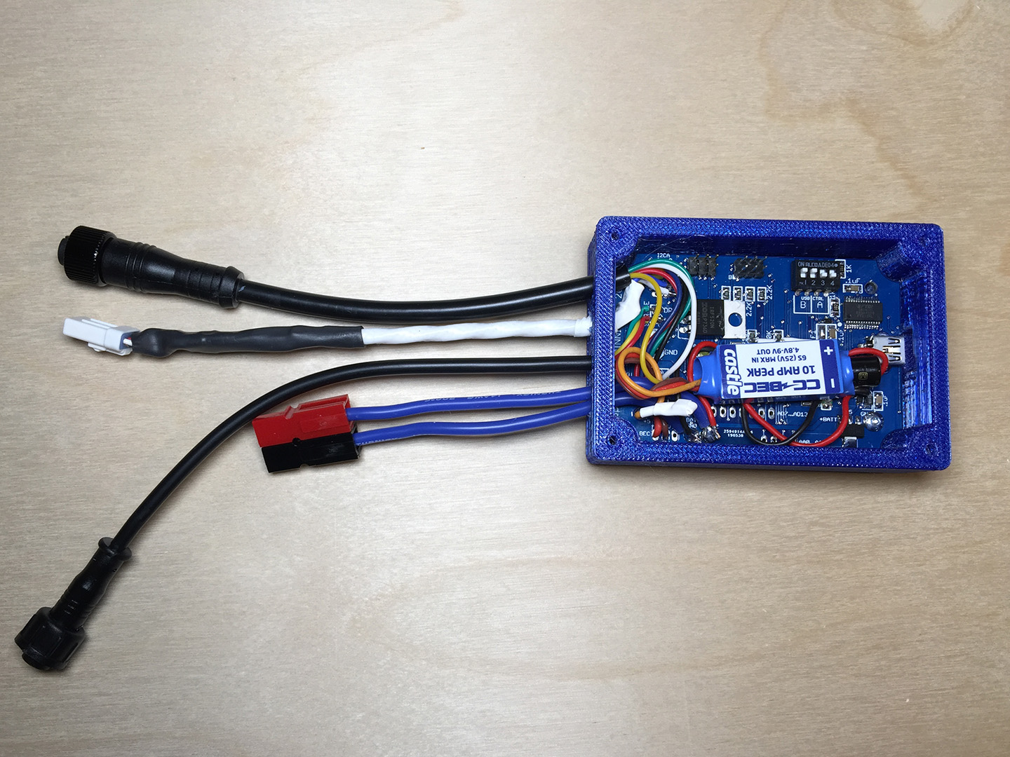
Inside the driver box. Custom PCB that I designed and had made. Also using a Castle Creation off the shelf 5V/10A buck converter to drive the ring LEDs.
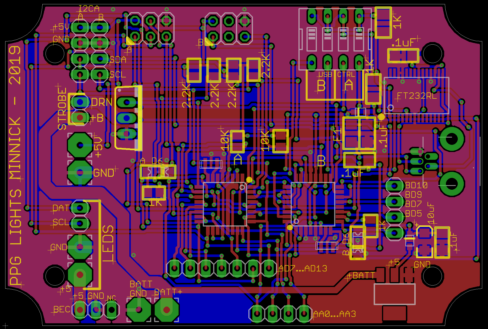
Cad view of the PCB...
My CAD design for the keypad's enclosure...
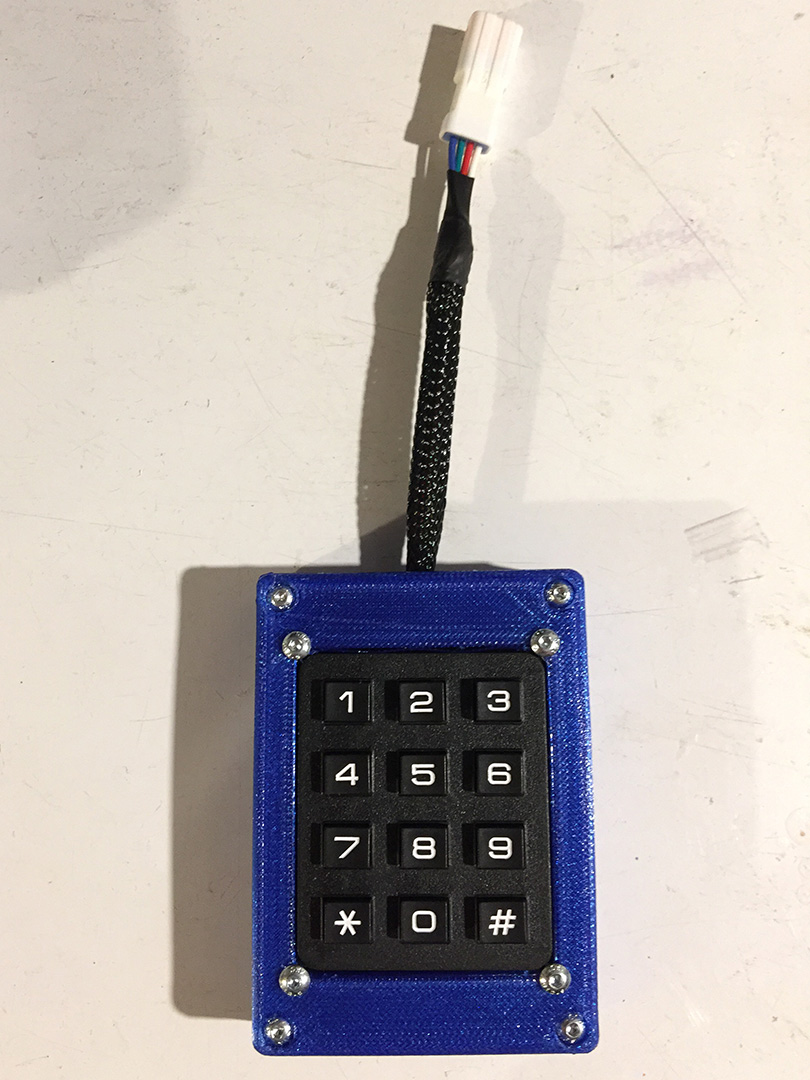
The finished modular keypad...
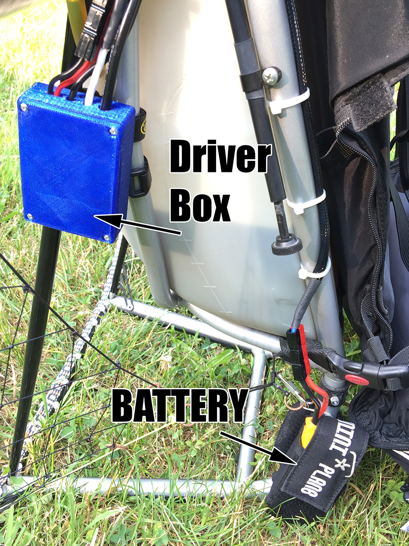
Driverbox and Battery mounted on my frame...
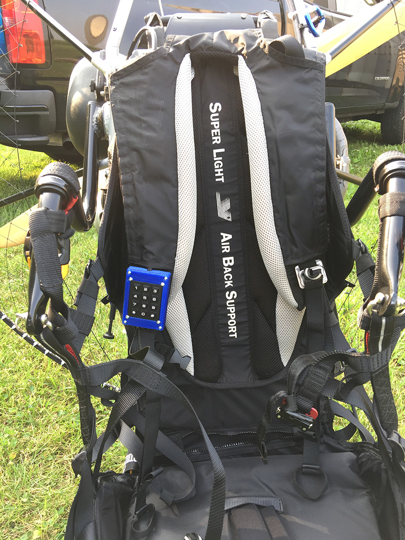
Keypad mounted to my harness so that I can reach it in flight...
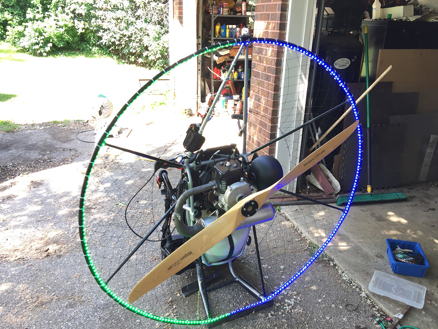
Testing out the lights on the ground...
Reader Comments