Sunday
Dec082013

Building a Travel Quad.

I am on the quest for the Holy Grail, or at least my version of it.  I am looking to visit some friends in Hawaii sometime next year and I am looking for the perfect drone to take with me to capture video of some of the more scenic areas there.   My requirements are as follows...

  • Must be as small as possible for travel
  • Must get decent battery life (10mins is the goal)
  • Must be able to carry a Go-Pro camera
  • Must have smooth video
  • Must be stable in the air and fly well

This quad which I have named the "Aloha Quad" aims to fit that bill.  It is based on the Flite-Test rotorbones knuckles which I have outfitted with my own custom modifications.

To reduce vibration,  I will use the necessary evil (Weight) that I must carry to my advantage.  There is no getting around it,  I must carry a battery, camera, flight electronics, etc, but where I choose to place them might work to help eliminate vibration.

Taking a cue from the QAV 500, it seems that having a vibrationally "dirty" section where your motors, and props are isolated from the "clean" section where the electronics and camera reside might offer the best solution.

Here I present the first version RevA

OK, so what's going on here?  First I created a plate out of acrylic which I cut on the laser cutter down at Baltimore Hackerspace.  The idea is the plate will carry the weight of everything I can mount on to it which will provide inertial resistance.

This plate will be isolated from the rest of the frame using vibration dampeners.  I have a variety of different hardness dampeners to experiment with to determine which offers the best solution...

Ultimately this design failed.  As it turns out, the CG was too high which caused the drone to become quite unstable in flight.  See the following video for an example.


My idea to correct this is to relocate the plate to the bottom.  I am still putting the finishing touches on the design, once I have it finished, I will update my progress on this page.  Here is a render of what I have so far....

Saturday
Nov162013

Designing an Enclosure.

I recently prototyped a new project that I am ready to put into an enclosure.  I thought this would be a good time to document my design/fabrication process.


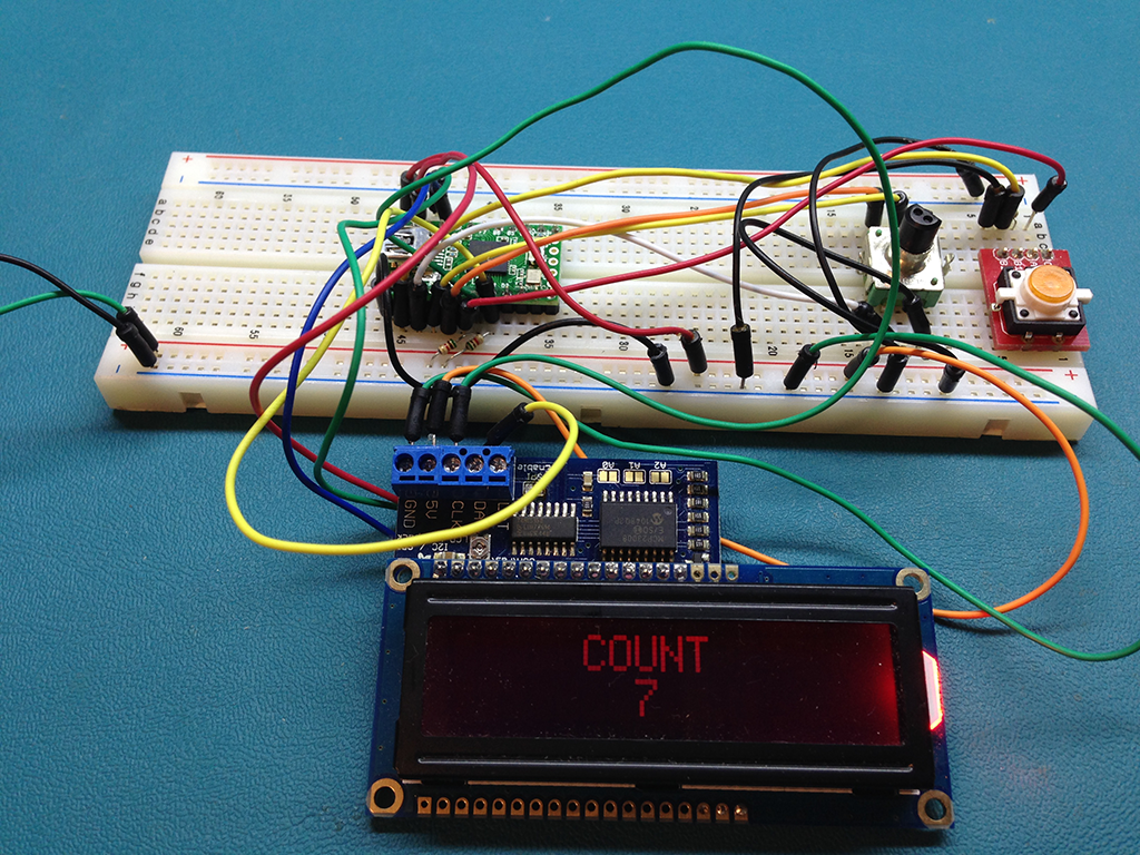
Here is the fully functioning circuit on a breadboard.

This is a mouse mover/clicker that I programmed to automate a redundant task at work.  Before you say "They have macro software applications for that" Yea, I know, however my employer does not permit me to install software on the workstations.  Anyhow, this post is about enclosure selection and design.

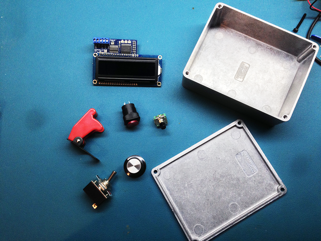
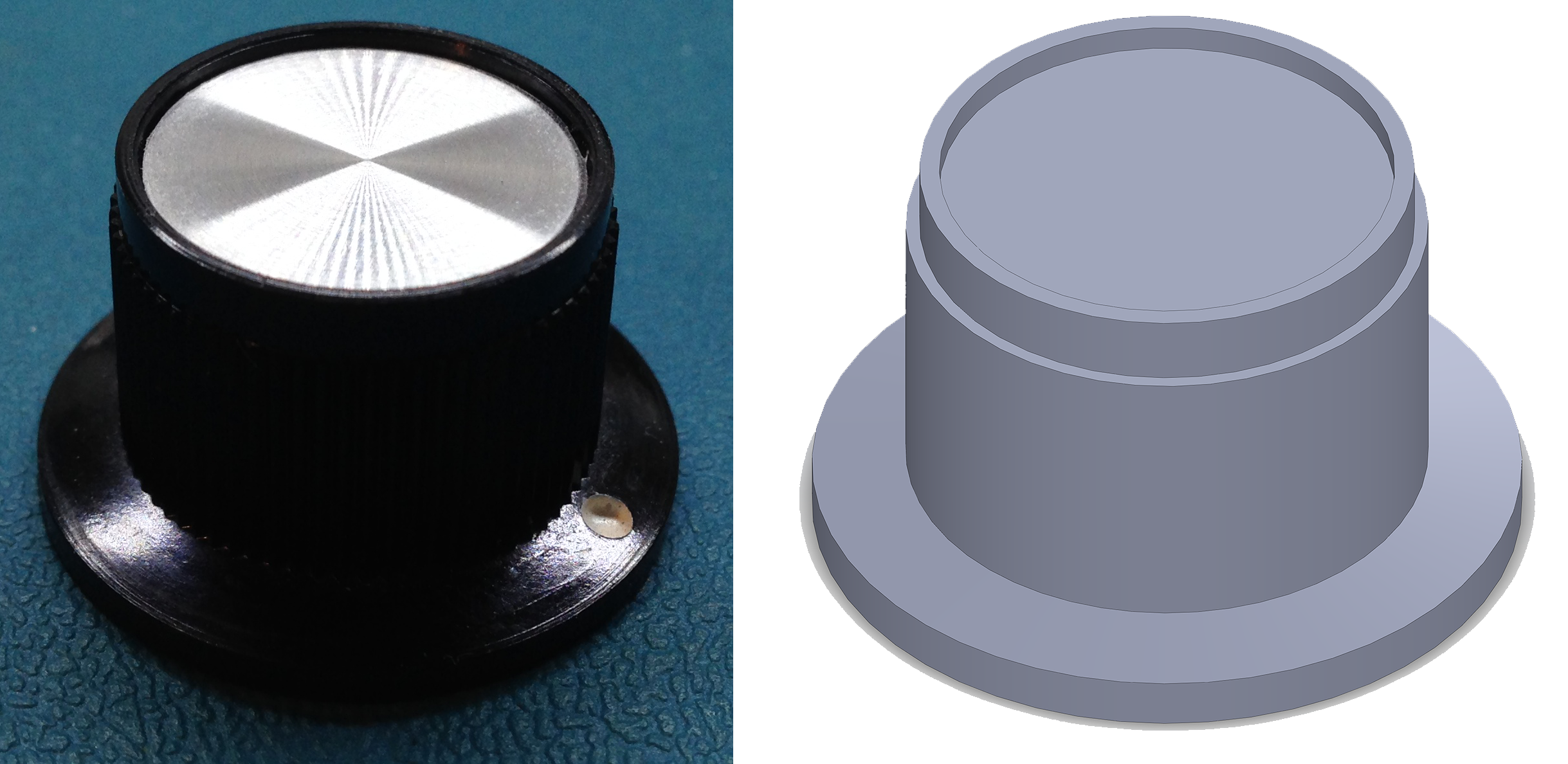
Here are all of the components I am going to mount.  An LCD Display, Illuminated Pushbutton, Rotary Encoder (with knob), Toggle Switch (with missile switch cover)

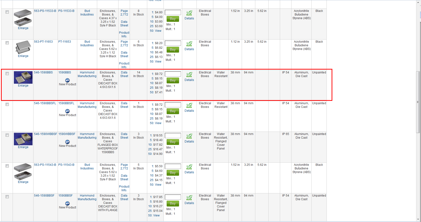
The first step is enclosure choice,  being as the longest part is the pushbutton (24mm) I use that as a starting point to narrowing my search on mouser.  I chose a range between 24mm and 2 inches (50.8mm).  I don't want the box to be too tall.  Next I need to consider the width of the LCD.  According to Adafruit, the width is 80mm which is ~3.14inches.  I decide to further filter my search from 3.25inches to 4inches wide...This narrows the search down to 14 items.  Scrolling down a see a nice Hammond Enclosure that looks like it might work, I’ve used their enclosures in the past and really like them.  They are high quality and not terribly expensive and they usually provide a ton of info on them.

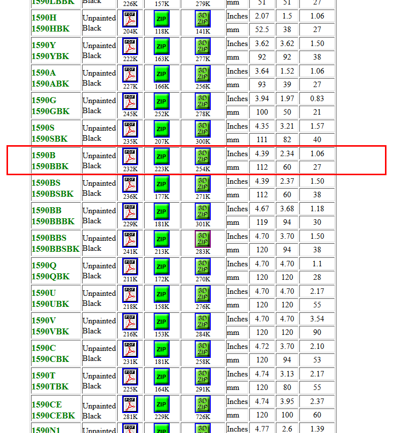
I go to the manufacturers website to check out the datasheet, and I find not only do they offer the dimensional data, they also provide cad files (3d.zip) for download!  Awesome!


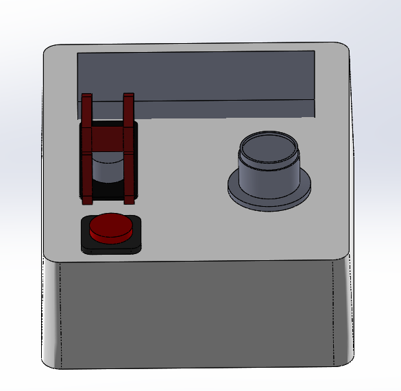
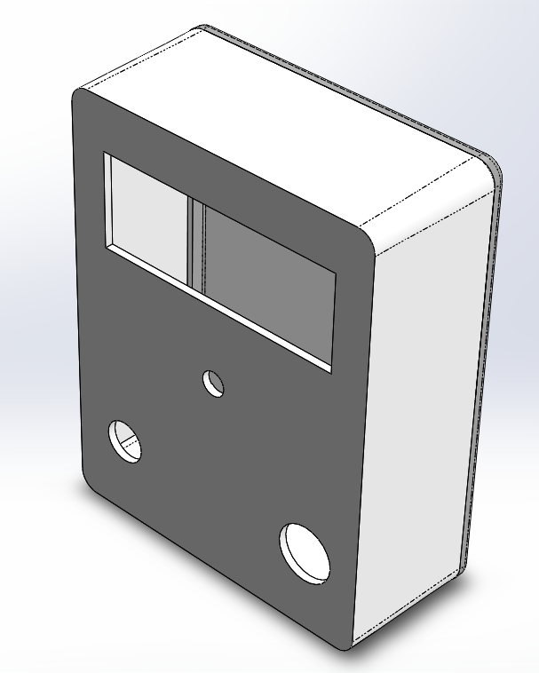
The next step is to fire up SolidWorks and model all of the components.  My goal isn't to create a perfect rendition, I am only concerned that the cutouts dimensions are accurate and that the render is "good enough" to give me a visual idea of how it will all look when it is finished.


After I have all the components modeled, it is time to start trying some arrangements...

Here I printed one out to scale to see how it looks in the real world..


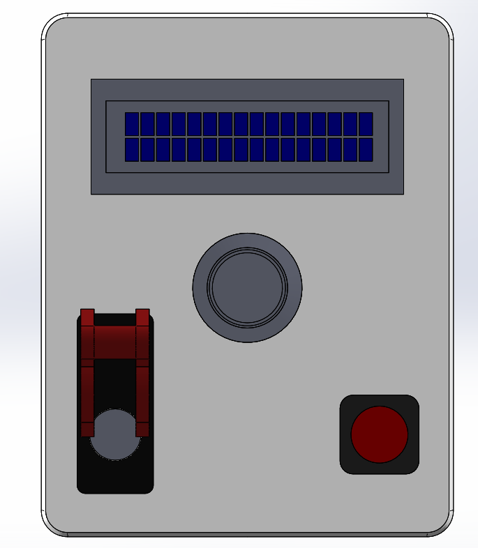
When I started simulating pressing the buttons and switches, I felt that the pushbutton was too close to the switch, it didn't seem natural, so I played around with the arrangement physically then went back to SolidWorks.  I ended up coming up with this final version...

There is decent spacing (as much as the small case will allow).  I aligned the knob on the center axis and the button and switch are aligned vertically.

I did another paper mockup, and it seemed nice, so I now hide all of the extra bits and leave only the cutouts.

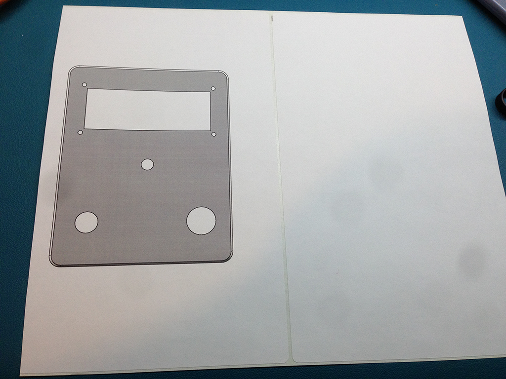
Next I print it on sticky backed labels...

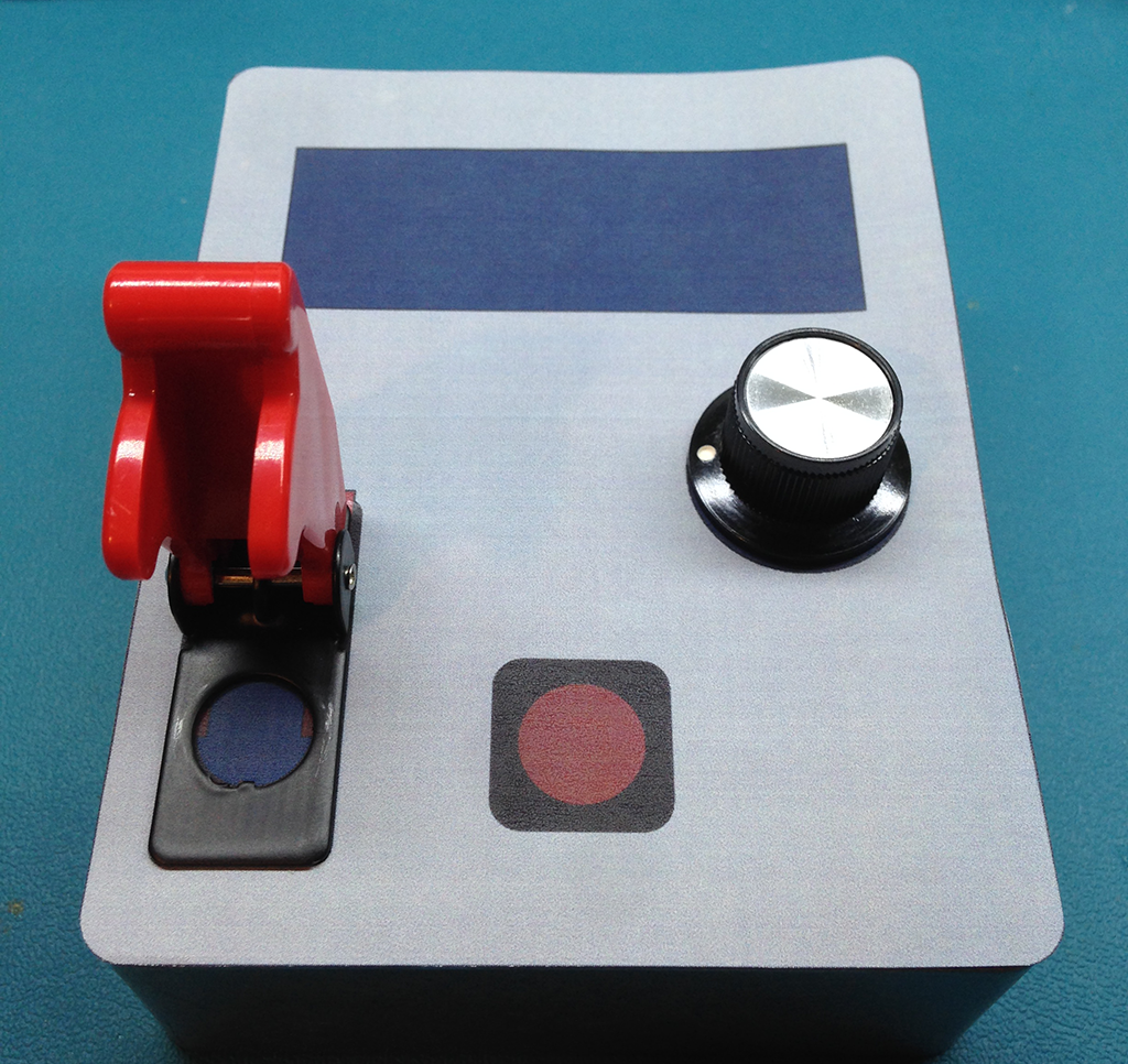
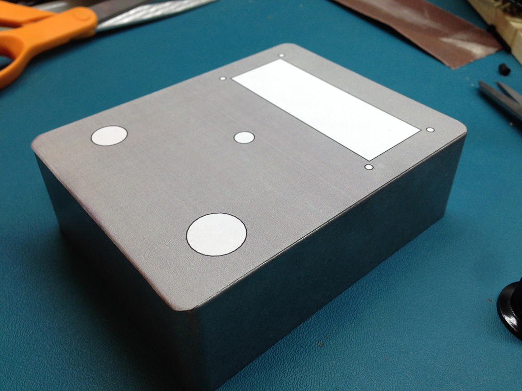
then I cut it out an stick it on to the case..

The label will not move, I can use this as a guide to make my drills and cutouts.  It will be a pain to remove, but since the case is metal, I can use acetone to help me.

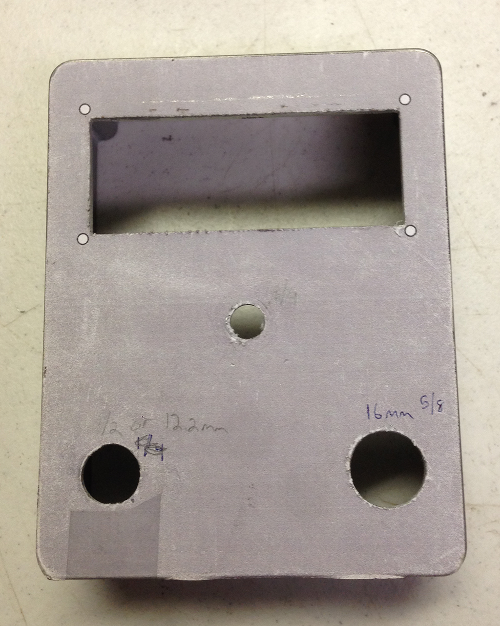
Milling and Drilling the case becomes a matter of following the pattern.  I forgot to take photos of the process, but I used an auto nibbler to rough out the rectangle for the screen and a drill press to drill the holes. 


I had to work the rectangle cutout with a file for a bit to get the fit perfect.  Overall I think it came out really well.  There is a large benefit to being able to virtually plan out the build before cutting the material

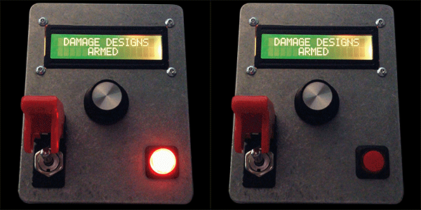
Here is an animated .gif of the final project..

Sunday
Sep082013

Neopixel Roulette Wheel

This was a simple little coding exercise I did for fun that simulates a mini roulette wheel on an Adafruit neopixel ring.  The code isn't perfect aesthetically, but it is functional. so go ahead, wire up 1 neopixel ring and let me know what you think!  below is a video of it running followed by the source code.  Alternately,  here is a link directly to the code.


     /*
    Neopixel Ring Roulette wheel sketch.
    "Spins" a roulette wheel and lands on a random value.
    I am not 100% satisfied with the aesthetic, but its as close as I can get.
    I would prefer a more realistic spinning to a slow effect with the final numbers slowly dropping onto a value
    similar to the price is right money wheel.
    I tried several approaches, but I can not seem to nail it.
    A linear increment of a delay does not look right

    If anyone can improve upon it,  I would love to see what results they come up with.
    If you make it improve it, let me know at tom[at]damage[dot]cc
    It would be rad to build a full 36+2 position American style roulette wheel out of neopixels!


    Code is based on the adafruit neopixel 'strandtest' code.
    */


    #include <Adafruit_NeoPixel.h>
    long randNumber;  //variable to hold random number value
    int pos;          //used to track position of lit segment


    //──────────────────────┤         User Variables          ├────────────────────────────

    #define PIN 6     //data pin used in for neopixel
    int spins = 6;        //how many times to 'spin before starting to slow down and settle
    #define dir 1  //set to 1 for clockwise rotation, 0 for counter clockwise.

    //───────────────────────────────────────────────────────────────────────


    // Parameter 1 = number of pixels in strip, value at 16 for NeoPixel Ring.
    // Parameter 2 = pin number (most are valid)
    // Parameter 3 = pixel type flags, add together as needed:
    //   NEO_KHZ800  800 KHz bitstream (most NeoPixel products w/WS2812 LEDs)
    //   NEO_KHZ400  400 KHz (classic 'v1' (not v2) FLORA pixels, WS2811 drivers)
    //   NEO_GRB     Pixels are wired for GRB bitstream (most NeoPixel products)
    //   NEO_RGB     Pixels are wired for RGB bitstream (v1 FLORA pixels, not v2)
    Adafruit_NeoPixel strip = Adafruit_NeoPixel(16, PIN, NEO_GRB + NEO_KHZ800);


    //──────────────────────┤       SETUP Function       ├────────────────────────────

    void setup() {
      randomSeed(analogRead(1+2+3+4+5));  //initialize floating pin (analog pins 1-5) as the seed for the RNG
      strip.begin();
      clr();  //clear the display for good measure.
      strip.show(); // Initialize all pixels to 'off'
    }


    //──────────────────────┤         Main Loop          ├────────────────────────────

    void loop() {

      randNumber=random(0,16);  //fetch a random number between 1-16

      //call the wheel
               //color used for for odd segments, even segments, and for '0'
      roulette(strip.Color(48,0,0),strip.Color(0,0,48),strip.Color(0,48,0));   
    }


    //──────────────────────┤  Roulette Wheel Function   ├────────────────────────────

    void roulette(uint32_t c,uint32_t d,uint32_t e) {

        //spin the number of times (variable 'spin') at full speed
          for (int i=0; i<16*spins; i++){
               advanceOne(c,d,e, 4);
          }   
         
          //slow down and 'settle' on final number
          for (int i=0; i<(16*6)+randNumber; i++){
               advanceOne(c,d,e, (i*.25)+4);
          }

    //optional press reset button to spin.
    //while(1);    //wait indefinitely,  press reset button on Arduino to spin again.
      delay(2000);  //reset spins automatically.

    } //end 'roulette' function


    //──────────────────────┤ Advance One Position Function ├────────────────────────────

    //every time this function is called, the led is advanced 1 position on the wheel
    void advanceOne(uint32_t c,uint32_t d,uint32_t e, uint16_t wait) {


                clr();//Clear the display

                  if ((pos & 0x01) == 0) {    //check to see if position is an even number
                        strip.setPixelColor(pos, c); //turn on the pixel at position 'pos'
                   } else  //else it is odd
                     {strip.setPixelColor(pos, d);
                   }

                  if (pos == 0) { //or check to see if it is '0'
                     strip.setPixelColor(pos, e);
                   }

                strip.show();
                delay(wait);

                if (dir){    //if direction var is set to clockwise
                      pos--;  //decrement the position
                      if(pos<0)  {pos=15;}  //resets running count if < 0}
                }
                    else{
                      pos++;  //increment the position
                      if(pos>15)  {pos=0;}  //resets running count if > 15}
                }

    }//end advanceOne function


    //──────────────────────┤ Clear all Pixels Function ├────────────────────────────

    //clears the display
    void clr(){
      for(uint16_t i=0; i<strip.numPixels(); i++) {
        strip.setPixelColor(i, 0);
        strip.show();
      }
    }

Saturday
Jan122013

Futaba Transmitter Mod (Fly E-flite Bind and Flys!)

Disclaimer:  Open your radio at your own risk.  I claim no responsibility for any damage caused or warranties voided.


I recently modified my Futaba 10C Radio (non-module version) to accept a Spektrum DSM module.  Here is a video overview of the project...


The idea originally came from reading this page on connecting a Dragonlink module.  I did not follow their instructions, However I did use their pin-out shown here...


Based upon this, I wired a 4 conductor audio jack into the transmitter.  Since I wasn't able to thread the nut on, I used some J.B. Weld to secure the jack into place.


The wire colors are as follows...

Yellow: PPM

Red: +V

Purple: Ind

Black: Ground


Similarly inside the module, I connected another jack.


Here are the finished versions...


I accidentally cracked the enclosure for the module while drilling out the hole.  I CA glued it back into place.  It seems to be holding pretty well.


If you have any questions please comment below and I will try to fill in more details.


Wednesday
Jan022013

Snes Controller Mod (Well really, just stuffing a bunch of S&%# into a SNES controller.

I wanted to write a quick post about a fun and easy project I did back before I started this website.  Apologies for not documenting the full process, but this post is more about the idea, as there isn't much to the process itself.  This should be fairly easy for anyone comfortable with basic soldering and doesn't mind working with a dremil tool

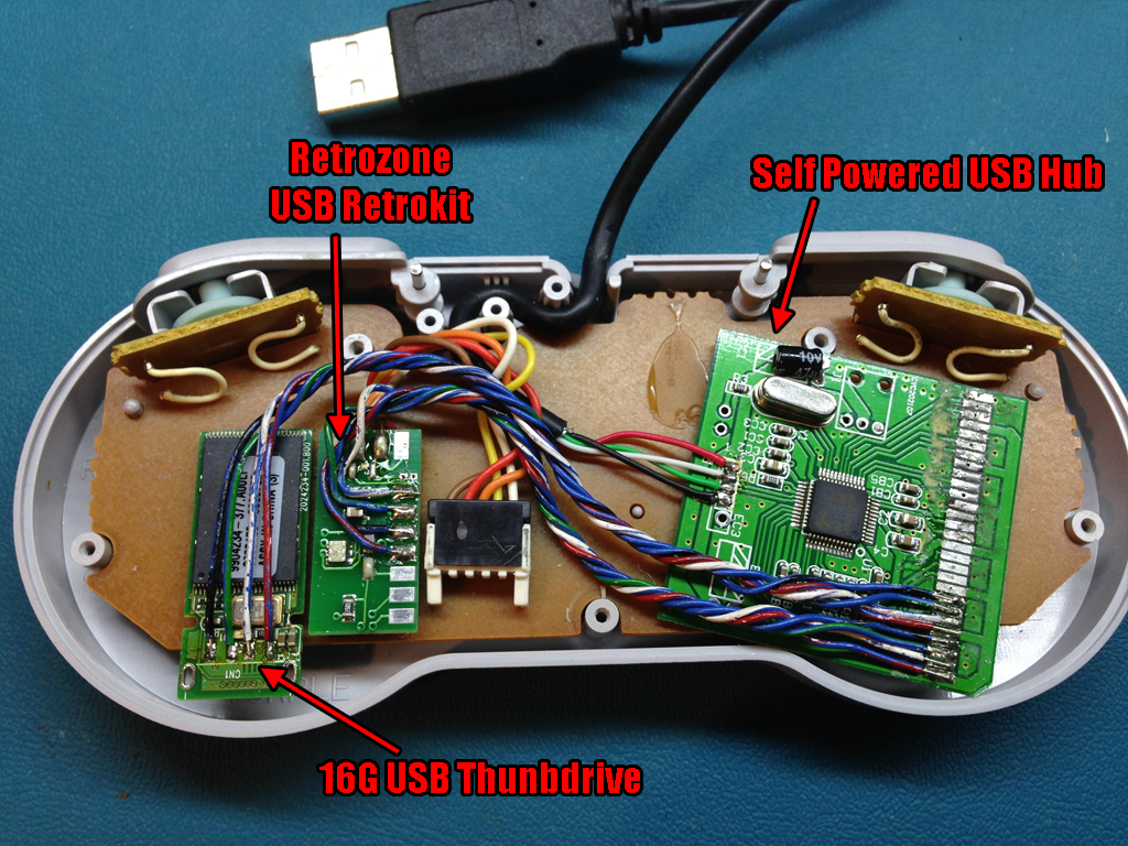
I like the idea of being able to run emulated games but still being able to use the original controller.  Retrozone sells a nice board that you can drop into your favorite controller and do just that.  However I wanted to take it a step further by including a way to store the emulator files with the gamepad.  This is what I have come up with...


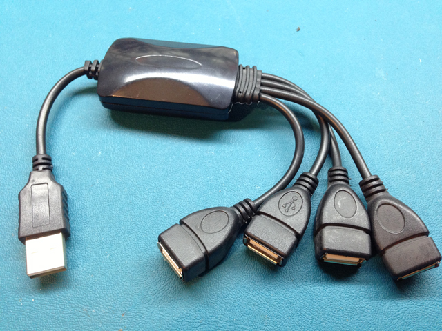
To connect multiple USB devices to the same port, We need to use a hub, since I wanted this to be all in one.  At first I looked into designing a small USB hub, but then I found these small "squid" style cheapo hubs from china, so why re-invent the wheel? The ones I found were only a few dollars a piece, so the price was right.  Pick up a few incase you botch one and to justify the shipping costs.  Also, get a 4 port hub, not more.  The 4 port hubs will usually have a smaller circuit board.  Search around, any hub will do so long as it is "self powered" (doesn't use an external power brick) and you can get it to fit.  Here is a picture of the one I used...


Being as the components only pull a few 100mA's of current, power should not be an issue.  I took apart the hub and a 16G thumbdrive and removed all the casing and extra plastic bits so I could save precious space.  I then wired all of the connections point to point.  If you attempt this, you will likely need to mill some of the plastic bits inside the controller to get it to fit.  Once I got it screwed back together, you would never know it had all this stuff in it aside from the USB plug on the end of the wire.

The end result... You plug in the controller, it shows up in windows as a "plug and play" gamepad, and the drive pops up with all the files needed to run the emu.  This all means less fuss searching for where you put the files and more focus on what's important,  gaming.  Plus, since everything is on the controller, you can move it to a different PC and not lose your saves.  Eventually I want to do the same with other systems.