I recently prototyped a new project that I am ready to put into an enclosure. I thought this would be a good time to document my design/fabrication process.
Here is the fully functioning circuit on a breadboard.
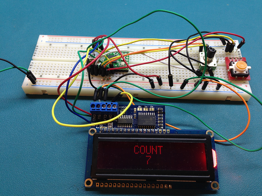
This is a mouse mover/clicker that I programmed to automate a redundant task at work. Before you say "They have macro software applications for that" Yea, I know, however my employer does not permit me to install software on the workstations. Anyhow, this post is about enclosure selection and design.
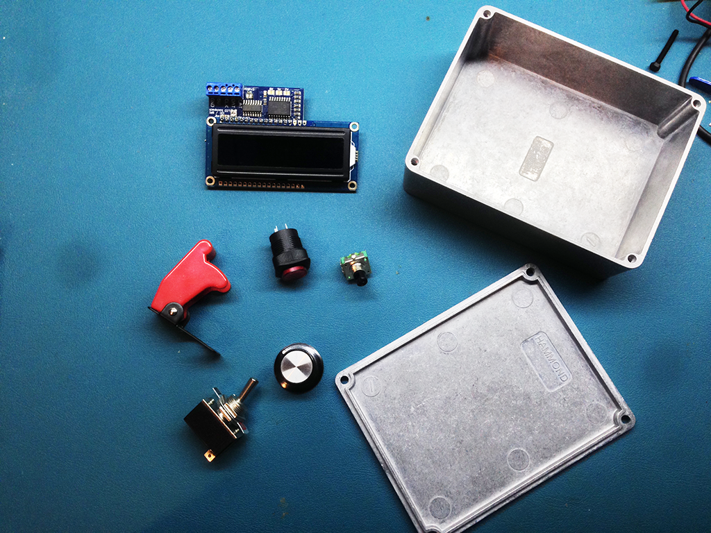
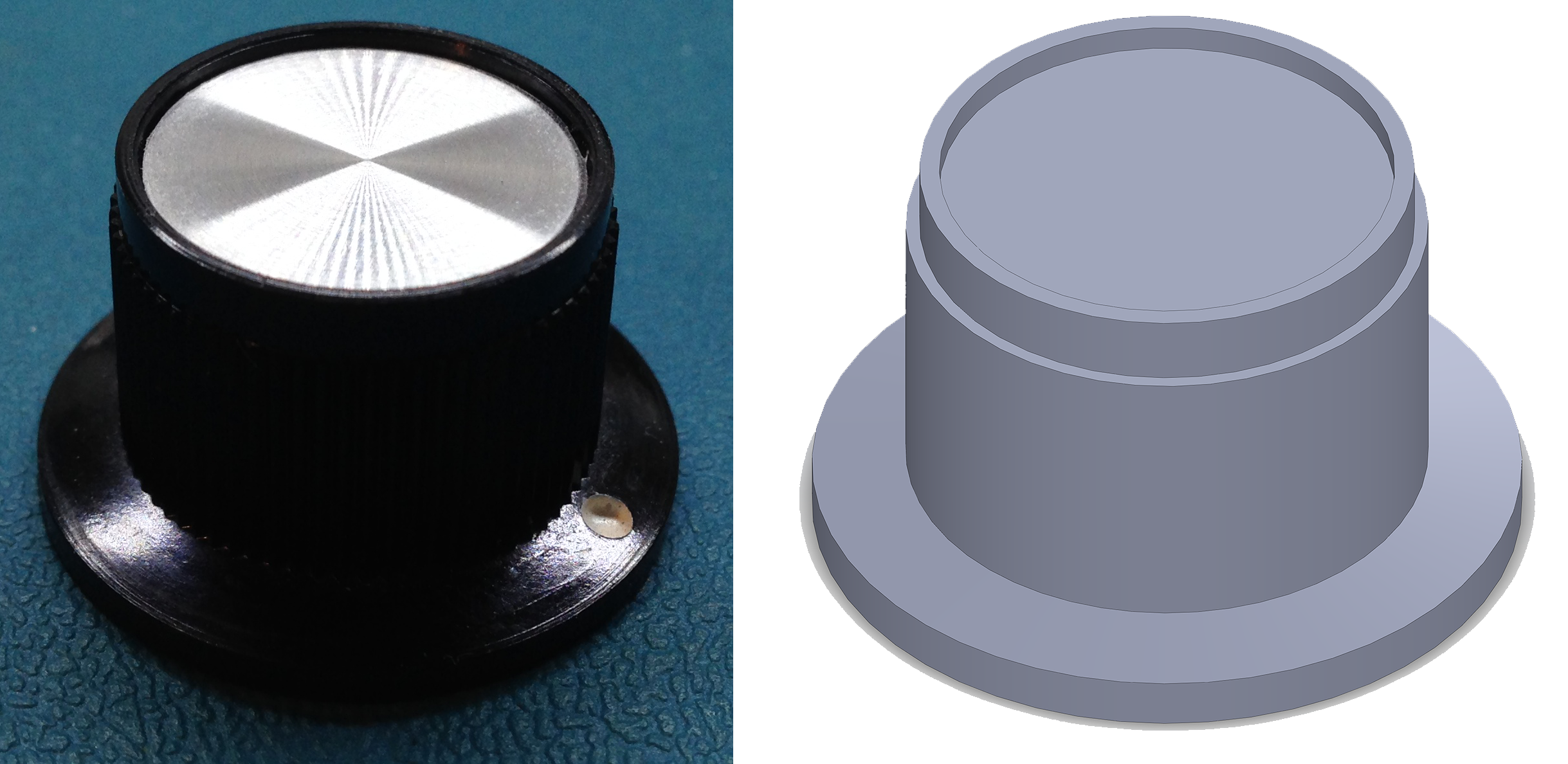
Here are all of the components I am going to mount. An LCD Display, Illuminated Pushbutton, Rotary Encoder (with knob), Toggle Switch (with missile switch cover)
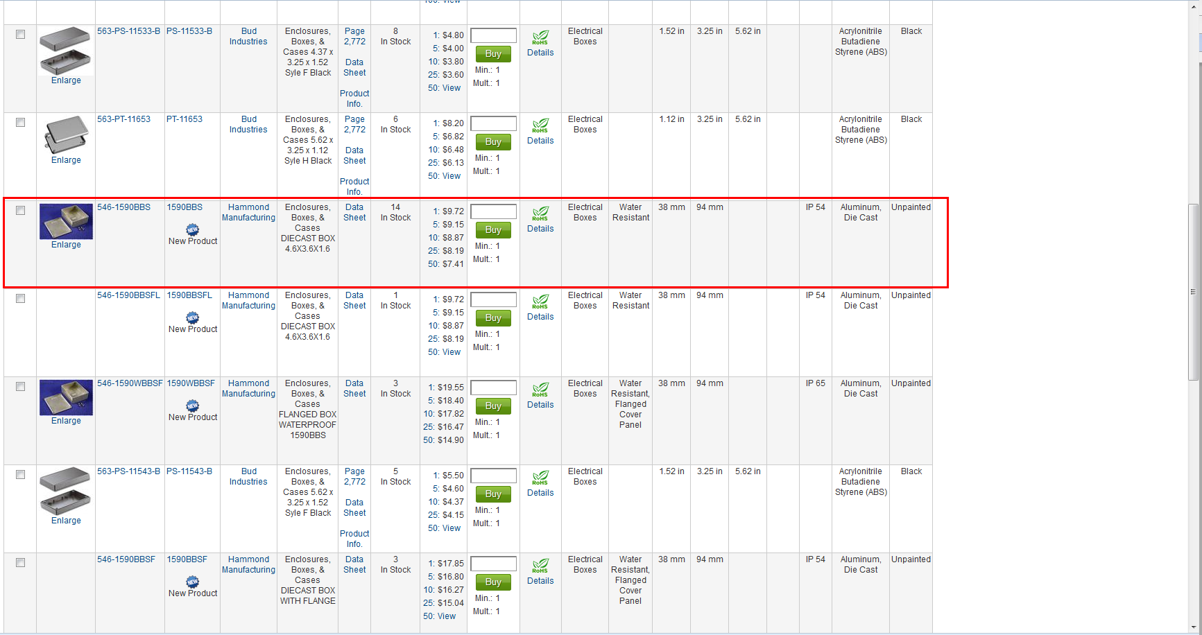
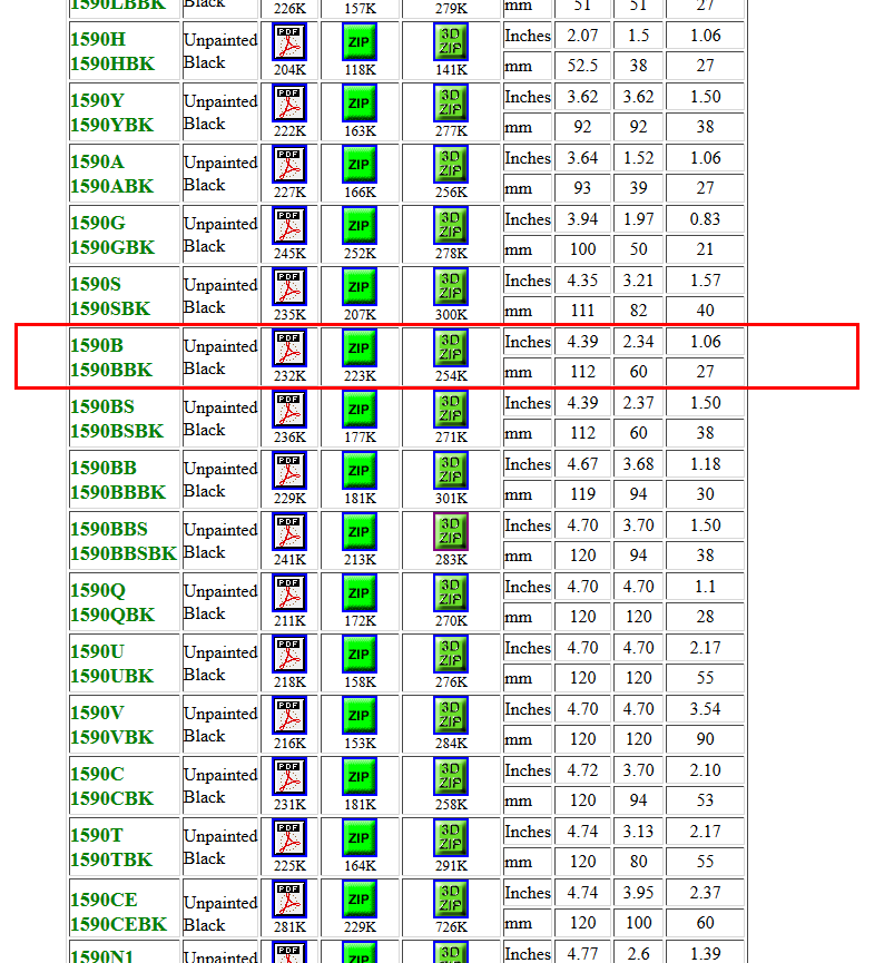
The first step is enclosure choice, being as the longest part is the pushbutton (24mm) I use that as a starting point to narrowing my search on mouser. I chose a range between 24mm and 2 inches (50.8mm). I don't want the box to be too tall. Next I need to consider the width of the LCD. According to Adafruit, the width is 80mm which is ~3.14inches. I decide to further filter my search from 3.25inches to 4inches wide...This narrows the search down to 14 items. Scrolling down a see a nice Hammond Enclosure that looks like it might work, I’ve used their enclosures in the past and really like them. They are high quality and not terribly expensive and they usually provide a ton of info on them.
I go to the manufacturers website to check out the datasheet, and I find not only do they offer the dimensional data, they also provide cad files (3d.zip) for download! Awesome!
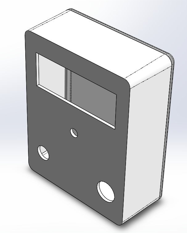
The next step is to fire up SolidWorks and model all of the components. My goal isn't to create a perfect rendition, I am only concerned that the cutouts dimensions are accurate and that the render is "good enough" to give me a visual idea of how it will all look when it is finished.
After I have all the components modeled, it is time to start trying some arrangements...
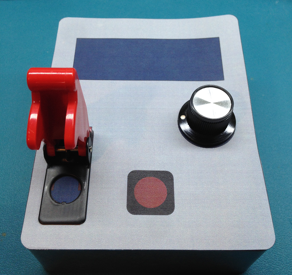
Here I printed one out to scale to see how it looks in the real world..
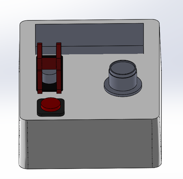
When I started simulating pressing the buttons and switches, I felt that the pushbutton was too close to the switch, it didn't seem natural, so I played around with the arrangement physically then went back to SolidWorks. I ended up coming up with this final version...
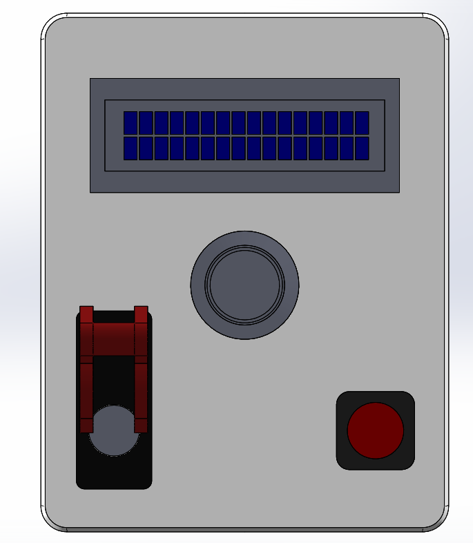
There is decent spacing (as much as the small case will allow). I aligned the knob on the center axis and the button and switch are aligned vertically.
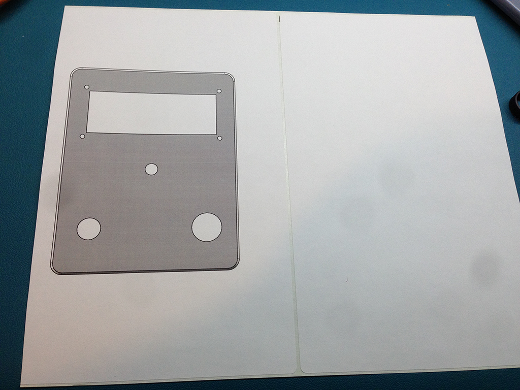
I did another paper mockup, and it seemed nice, so I now hide all of the extra bits and leave only the cutouts.
 Next I print it on sticky backed labels...
then I cut it out an stick it on to the case..
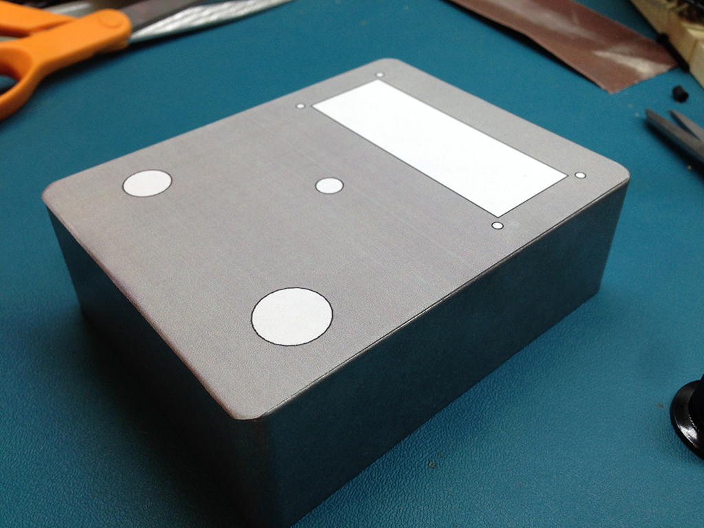
The label will not move, I can use this as a guide to make my drills and cutouts. It will be a pain to remove, but since the case is metal, I can use acetone to help me.
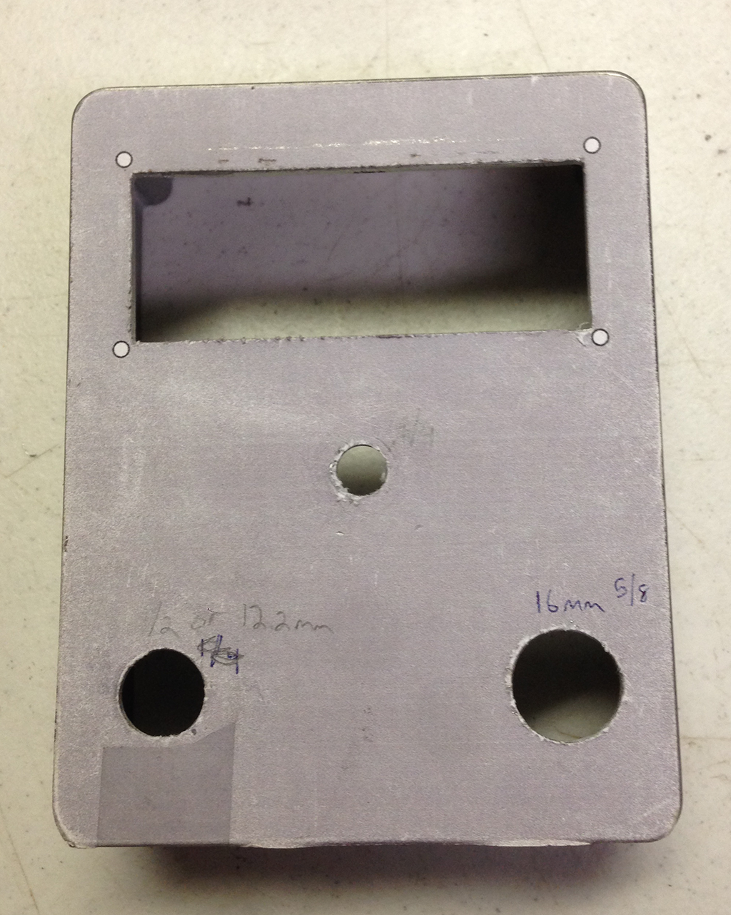
Milling and Drilling the case becomes a matter of following the pattern. I forgot to take photos of the process, but I used an auto nibbler to rough out the rectangle for the screen and a drill press to drill the holes.
I had to work the rectangle cutout with a file for a bit to get the fit perfect. Overall I think it came out really well. There is a large benefit to being able to virtually plan out the build before cutting the material
Here is an animated .gif of the final project..